Krrass customer support team is here to answer your questions. Ask us anything!
Hi, how can I help?
FSCUT2000 is a high-performance open loop laser control system developed independently by Shanghai Friendess Electronic Technology Co., Ltd. It is widely used in the field of metal and non-metal laser cutting. Because of its outstanding performance in the field of medium power fiber laser cutting, it is favored by a large number of high quality customers.
Please read the manual carefully before using the controller and relevant devices. FSCUT2000 laser cutting control system is composed of standard accessories as shown below:
| Name | Model | Amount |
| Motion-controlled card | BMC1604V2 | 1 |
| Terminal board | BCL3766 | 1 |
| Extension cable(with block) | C37-40 | 1 |
| 37-pin cable (2m) | C37-2 | 1 |
| 62-pin cable (2m) | C62-2 | 1 |
| Servo cable (1.5m) | C15-1.5 | 4 |
| Laser software | CypCut 1 | 1 |
| WKB | WKB | 1 |
| CNC panel(matching) | BCP5045 | 1 |
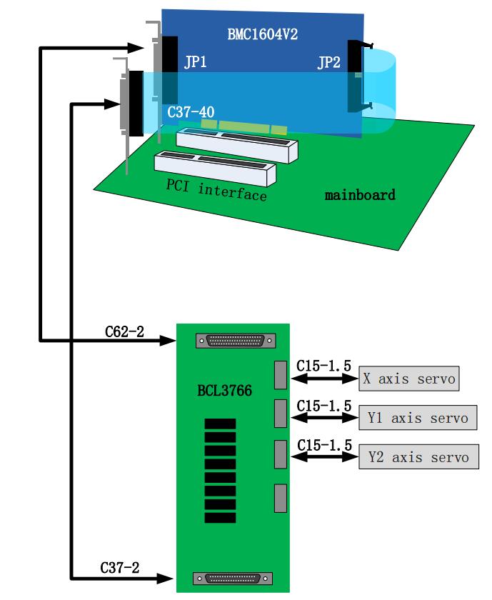
BMC1604V2 applies PCI interface whose external size is 213mm*112mm. The control card has two sockets,JP1 is a DB62M socket with matched C62-2 cable connected to BCL3766 External IO board; JP2 is an external expansion cavel socket, with C40-37 expansion winding displacement (with a guard sheet) connected to the back of computer case firstly, and then with C37-02 cable connected to BCL3766 External IO Board.
The system wire is shown as below:
| Item | Description | |
| Motion control | Motor control signal | 4 axis with high-speed pulse output and maximum frequency3MHz |
| 3 axis with encoder feedback channel and four times frequency up to 8MHz | ||
| The original point of every axis with limit, servo alarm special input signal. | ||
| The servo performance of every axis, alarm clear special output signal. | ||
| Motor control performance | Control cycle is 1ms. | |
| “S” speed-up and speed-down with wave filtering. | ||
| Velocity look-ahead, inflection point with intelligent speed-up and speed-down. | ||
| The speed limit of small circular arc, Local curvature analysis | ||
| The smoothing of turning | ||
| Laser control signal | Output 1 is PWM signal, with dip switch choosing Laser control signal 24V or 5V. | |
| Output 2 is 0~10V analog signal | ||
| I/O Function | 12 general inputs. | |
| 20 general outputs, thereto, 8 interfaces are relay outputs,12 interfaces are mosfet emitter outputs. | ||
| Work environment | Temperature: 0~55℃ | |
| humidity: 5%~90%, no condensation | ||
| Power requirement | 24V,2A | |
Note: Please be careful, and effectively touch grounded metal parts before touching control card system or inserting/removing control card, in order to prevent static electricity from damaging motion control card, and please wear electricity-proof gloves.
(1) Shut down computer, insert control card into PCI slot, and fix control card and catch screw of expansion winding displacement.
(2) After start the computer, the window of “Driver Software Installation” pops up; click “Close” button as shown below. If this window does not pop up, it means control card is not inserted correctly. So please repeat step one.
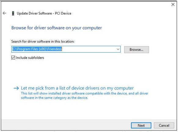
(3) Install CypCut software, while BMC 1604V2 card driver and softdog driver will be installed automatically.
(4) During installation, please close the anti-virus software, any block pop-up information in the process of installation shall be allowed to pass.
(5) Open the device manager to confirm the success of installation. If the following icon appeared:
![]() It shows that the installation was successful.
It shows that the installation was successful.
(1) If after starting the computer, the widow of “Found New Hardware Wizard” does not pop up, or control card cannot be found in device manager, which means control card is not inserted correctly. Please replace PCI slot or computer, insert and fix control card, and then reinstall the software.
(2) If there is yellow exclamation mark in the device, please double click ![]() open attribute page and select “details”, as shown below.
open attribute page and select “details”, as shown below.
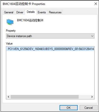
(3)If the first half of “device instance ID” attribute is ![]() ,which means the computer correctly identifies motion control card and software installation may fail. Please reinstall Cypcut software. If it fails again, please contact our technician.
,which means the computer correctly identifies motion control card and software installation may fail. Please reinstall Cypcut software. If it fails again, please contact our technician.
( 4 ) If the first half of “device instance ID” attribute is not “ ![]() ”, which means the computer doesn't identify motion control card successfully. Please shut down the computer, replace the PCI slot, fix the control card again, and then reinstall the software.
”, which means the computer doesn't identify motion control card successfully. Please shut down the computer, replace the PCI slot, fix the control card again, and then reinstall the software.
(5)If step four still fails, control card may have be damaged. Please contact our technician.
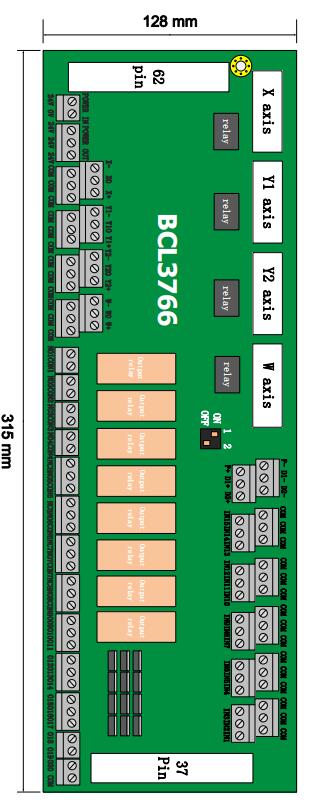
The External IO Board of BCL3766 is installed by rail and also can be installed permanently. Its external size is 315mm*128mm with DM62M and DB37M interface in two sides, corresponding to JP1 and JP2 of BMC1604V2. C62-2 cable is used to connect External IO Board DB62 interface with JP1 port on the back of control card JP2 interface is linked by C37-40 baffle wire and then is fixed on erection fixture of computer with bolts. And C37-2 cable is used to connect DB37 socket on External IO Board.
The four DB15M interfaces on the top left corner are servo control signals, which are X axis, Y axis and W axis, respectively, from left to right. When being used as gantry dual drive, W axis is as Y2 axis. When being used as pipe cutting, W axis is as rotation axis.
High-low terminals on bottom left are respectively limit and origin signal of X axis and Y axis. High-low terminals on upper right are origin and limit input of W axis and general input interface, with all the low terminals break-over, as COM ground, namely 0V.
The interface on bottom right is 20 general outputs, thereto, 8 outputs as relay output, 12 outputs as mosfet output. The first 4 ones of the 8 relay outputs only have normally open contacts and the second 4 outputs have normally open contacts and the second 4 outputs have normally open contacts and normally closed contacts. The 8th mosfet output is 24 V general cathode output.
The three 2--pin terminals over right above are 1 PWM and 2 DA analog signal.
Dip switch:
There is a 4-bit dip switch below the PWM and DA analog signal. Its usage is shown as below :
The first bit (P1) and second bit (P2) of 4-bit dip switch choose PWM voltage.
| P1 | P2 | Implication |
| On | Off | PWM voltage is 24V |
| Off | On | PWM voltage is 5V |
Input signals include: limit, origin and general input. The input of BMC1604 V2 card is active low level: support normally open and normally closed mode (The polarity of input port can be modified by “platform configuration tool” of CypCut software). When the setting is normally open, input port and 0 V break-over are active; when the setting is normally closed, disconnection of 0 V is active.
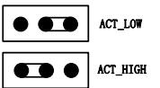
Input port polarity can be modified through the hardware jumper. Now IN13, IN14 and IN15 input ports support this function. Jumper has two states, ACT_LOW as shown in the figure, which means low level is active (inputting 0V voltage is active); ACT_HIGH as shown in the figure, which means high level is active (inputting 24V voltage is active). Default state is ACT_LOW.
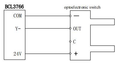
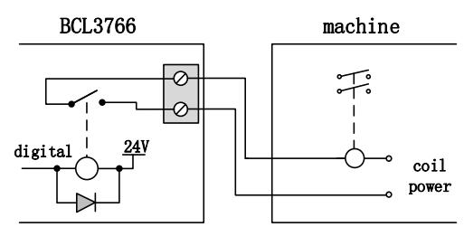
Typical connection of optoelectronic switch is shown as below, which must use 24V switch of the NPN type (low level is active).
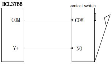
Typical connection of contact switch is shown as below:
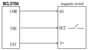
Typical connection of magnetic switch is shown as below, which must use 24V switch of the NPN type.
Load capacity of relay output contact on External IO Board is: 240VAC/5A, 30VDC/5A. Controllable small power is 220 V alternating load. Please connect contactor externally if connected with big power load.
The connection of relay output and contactor is shown as below:
There are OUT9~OUT20, total 12 outputs, mosfet emitter output on BCL3762-V5.0 External IO Board and it can directly drive 24V direct current device.
Each current supply capacity is 500mA. Typical connection is shown as below:

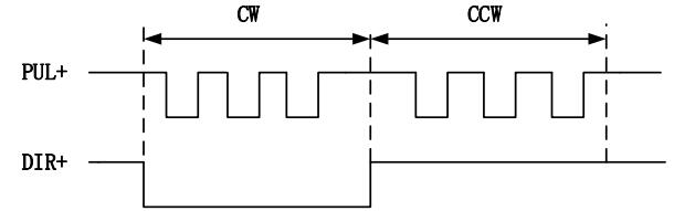
Pulse command state of control driver is “pulse+direction, negative logic”. The highest pulse frequency: 3MHZ. The pulse mode is shown as below:
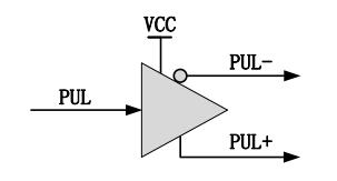
The output way of differential signal is shown as below :
There are 2 outputs of 0~10V analog signal in the External IO Board.
| Item | Description |
| Range of output signal | 0V~+10V |
| Maximum output current load | 50mA |
| Maximum output capacitive load | 350pF |
| Input impedance | 100KΩ |
| Maximum bipolar error | ±50mV |
| Resolution ratio | 10mV |
| Conversion speed | 400us |
BCL3766 External IO Board has 1 PWM pulse width modulating signal which can be used for controlling average power of fiber laser. PWM signal level is 5 V or 24 V for selection. Duty cycle is 0%~100% and the highest carrier frequency is 50 KHz. The output way of PWM signal is shown as below:
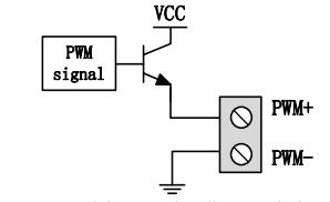
We strongly recommend that users install PWM+/- signal to a relay output port in series (Set it to PWM+/- enable signal.), then access to the laser, which can avoid laser light leakage in modulation mode. Please refer to “2.5 Laser Connection” for more details. Furthermore, please adjust PWM signal level. 24 V or 5 V level can be selected through dip switch.
External power source provide direct current 24 V for BCL3766 External IO Board. 24 V and COM of power input terminal are connected to 24 V and 0V of power output interface, respectively.
The four servo control interfaces on BCL3766 are DB15 two-row bores, and pin definition is as below:
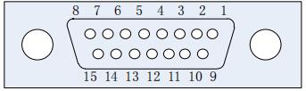
The signal definition of matched servo cables is shown as below:
| Pin | Line color | SignalName | Pin | Line color | Signal Name |
| 1 | Yellow | PUL+ | 9 | Yellow-Black | PUL- |
| 2 | Blue | DIR+ | 10 | Blue-Black | DIR- |
| 3 | Black | A+ | 11 | White-Black | A- |
| 4 | Orange | B+ | 12 | Orange-Black | B- |
| 5 | Red | Z+ | 13 | Red-Black | Z- |
| 6 | Green | SON | 14 | Purple | ALM |
| 7 | Green-Black | CLR | 15 | Brown-Black | 0V |
| 8 | Brown | 24V | / | / | / |
+24V,0V: Supply 24V DC power for servo drive; SON:
The output is servo enable signal when servo on; ALM:
Alarm, receive servo alarm signal;
PUL+, PUL-: Pulse (PULS), differential output signal;
DIR+,DIR-: Direction (DIR), differential output signal;
A+, A-, B+, B-, Z+, Z-: Three phase of encoder, input signal;
The polarity of SON and ALM signal can be modified through hardware jumper.
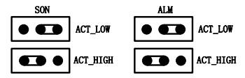
When the SON signal jump to ACT_LOW state, low level is active (inputting 0V voltage is active); When the SON signal jump to ACT_HIGH state, high level is active (inputting 24V voltage is active). Default state is ACT_LOW.
When the ALM signal jump to ACT_LOW state, low level is active (inputting 0V voltage is active); When the ALM signal jump to ACT_HIGH state, high level is active (inputting 24V voltage is active). Default state is ACT_LOW.
Please refer to “1.3.3 The wiring diagram of servo drive control signal” for connection of Panasonic, Yaskawa, Mitsubishi and Delta servo drivers.
Please pay attention to the following information when connect servo driver of other brands:
(1) Please confirm the type of servo driver SON signal you select whether low level is active or not. (That is, It is ON when connecting with 24V GND.)
(2) Confirm the parameters of servo driver are set as: the type of received pulse signal is “pulse + direction”
(3) Confirm whether t h e servo driver input terminal has external crash stopping signal input or not, and which logic the signal is.
(4) Before the trial operation of servo driver, 24 V power must be provided for External IO Board, for 24 V power servo driver needs is provided by External IO Board.
(5) If driver still cannot run, confirm that driver parameter is set as not using “positive & negative input inhibit”.
(6) Connect shielding layer of signal line with servo driver case.
FSCUT2000 motion control system apply the signal of “Pulse+Direction” to control servo driver. The pulse sending frequency cap is increased from the previous 750Kpps to 3Mpps.
Recommend using high-speed differential pulse signal, and setting the pulse equivalent of servo driver in 1000 ~2000, in order to improve the interpolation accuracy.
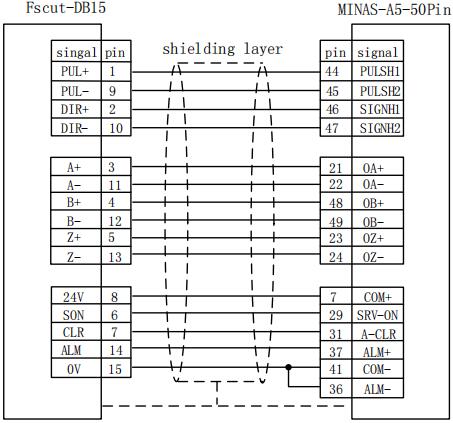
The wiring diagram of Panasonic A5 high-speed pulse
The wiring diagram of Panasonic A5 low-speed pulse
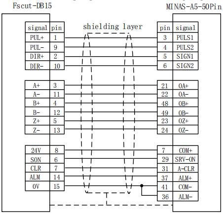
| Basic setting parameters of Panasonic A5 series | ||
| Parameter type | Recommender value | Implication |
| Pr001 | 0 | Control mode must be set as location mode. |
| Pr007 | 3 | Have to select “Pulse+Direction” mode |
| Pr005 | 1 | When using high-speed pulse connection mode, this parameter is set as 1, and the maximum supported pulse frequency is 3Mpps; When using low-speed pulse connection mode, this parameter is set as 0, and the maximum supported pulse frequency is 500Kpps; |
The wiring diagram of Yaskawa servo
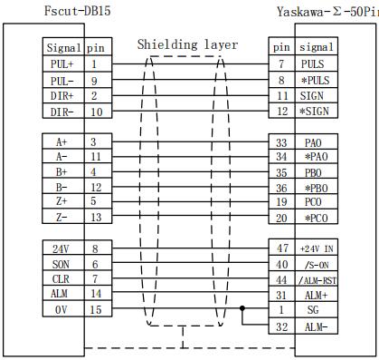
Basic setting parameters of Yaskawa Σ series
| Parameter type | Recommender value | Implication |
| Pn000 | 001X | Control mode must be set as location mode |
| Pn00B | None | When the input is single-phase power, modify into 0100 |
| Pn200 | 2000H | When the pulse frequency is lower than 1Mpps, please select 0000H mode; When the pulse frequency is up to1Mpps - 4Mpps, please select 2000H mode. |
| Pn50A | 8100 | Can be driven in co-rotation side |
| Pn50B | 6548 | Can be driven in reverse side |
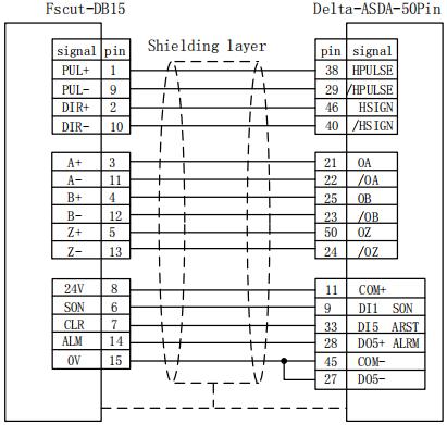
The high-speed pulse wiring diagram of Delta A series
The low-speed pulse wiring diagram of Delta A series
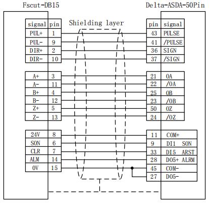
Basic setting parameters of Delta A series
| Parameter type | Recommender value | Implication |
| P1-00 | 1102H | Control mode, position control mode Negative logic pulse + direction. Set the parameters as: 1102H, the maximum pulse frequency is 4Mpps; Set the parameters as: 0102H, the maximum pulse frequency is 500K. |
| P1-01 | 0 | Select a position mode of external command control |
| P2-10 | 101 | DI1 is set a SON servo enabling, NO logic |
| P2-14 | 102 | DI5 is set as ARST clear alarm function, NO logic |
| P2-22 | 7 | DO5 is set as ALRM Servo alarm function NC logic |
The servo wiring diagram of Sanyo R series
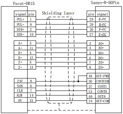
Basic setting parameters of Sanyo R series
| Parameter type | Recommender value | Implication |
| SY08 | 00 | Set as position mode |
| Gr8.11 | 02 | Select pulse signal input type: Pulse + direction; |
| Gr9.00 | 00 | Can be driven in co-rotation side |
| Gr9.01 | 00 | Can be driven in reverse side |
The wiring diagram of Schneider 23D high-speed pulse
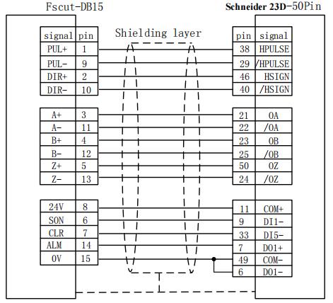
The wiring diagram of Schneider 23D low-speed pulse
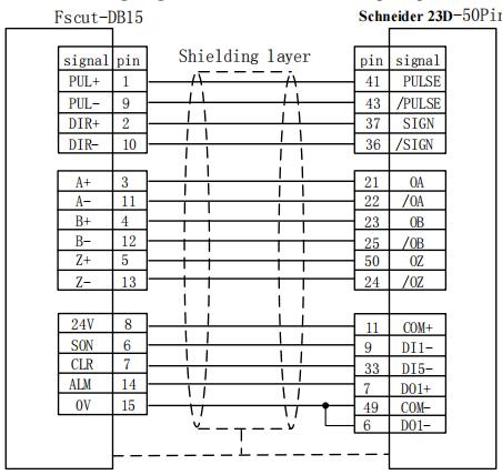
Basic setting parameters of Schneider Lexium 23D series
| Parameter type | Recommender value | Implication |
| P1-00 | 1102H | Control mode, position control mode Negative logic pulse + direction. Set parameters as: 1102H, the maximum pulse frequency is 4Mpps; Set the parameters as: 0102H, the maximum pulse frequency is 500K. |
| P1-01 | X00 | Position mode of external signal control |
| P2-10 | 101 | IN1 of servo is modified to SON function. |
| P2-11 | 0 | No using IN2 |
| P2-13~P2-17 | 0 | No using IN4~IN8 |
The wiring diagram of Fuji A5 series
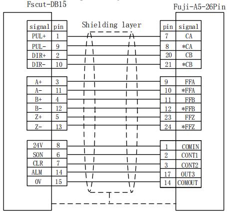
Fuji ALPHA 5 series
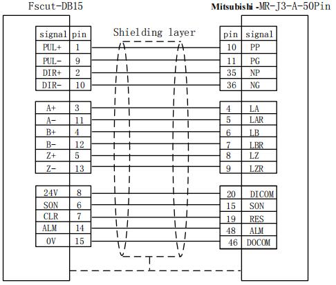
The wiring diagram of Mitsubishi J3 Series
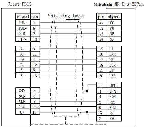
The wiring diagram of Mitsubishi E Series
The maximum pulse frequency of Mitsubishi J3 series is 1Mpps.
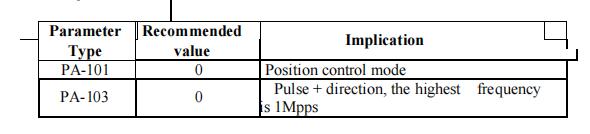
| Parameter type | Recommender value | Implication |
| PA-01 | 0 | Control mode-Position mode |
| PA-13 | 11 | Negative logic: Pulse+Direction |
Note:
Parameter settings above can guarantee basic sports only under the circumstances of the right wiring connection, not ensure control precision. And if you need to further optimize campaign results, please adjust the rigidity, gain, inertia ratio and other parameters.
Basic setting parameters of Mi Mitsubishi MR-J3 - A series
the limit of minus X direction, dedicated input signal and low level is active;
X0: the origin signal, dedicated input signal and low level is active;
X+: the limit of positive X direction, dedicated input signal and low level is active;
COM: GND, the general interface of the above three signals;
Y-: the limit of minus Y direction, dedicated input signal and low level is active;
Y0: the origin signal, dedicated input signal and low level is active;
Y+: the limit of positive Y direction, dedicated input signal and low level is active;
COM: GND, the general interface of the above three signals;
W-: the limit of minus W direction, dedicated input signal and low level is active; W0: the origin signal, dedicated input signal and low level is active;
W+: the limit of positive W direction, dedicated input signal and low level is active;
COM: GND, the general interface of the above three signals;
The input logic of limit and origin signal can be modified through “platform configuration tool” coming with the CypCut software. Please refer to chapter 3 platform configuration tool for more details.
There are 15 general inputs with IN1~IN15. 15 general inputs can be configured as various custom buttons or alarm input through “platform configuration tool” coming with the CypCut software. Please refer to chapter 3 platform configuration tool for more details.
There are 8 relay outputs with OUT1~OUT8. 8 relay outputs can be configured as the control port corresponding to “laser”, “auxiliary gas”, “height controller”, “indicator light” through “platform configuration tool” coming with the CypCut software. Please refer to chapter 3 platform configuration tool for more details.
When BCL3766 External IO Board is selected, besides 8 relay outputs, there are also 12 mosfet outputs, which can directly drive 24V direct current device.
DA1 and DA2 are 2 outputs of 0~10V analog signal. DA1 and DA2 can be configured as a control signal of controlling the laser peak power and proportional valve through “platform configuration tool” coming with the CypCut software.
When the laser type is configured as “fiber laser” through “platform configuration tool” coming with the software, PWM output port will be activated and used for controlling fiber laser average power.
When PWM is controlled needing to use 5V, 1 pin of four bit dip switch is OFF, and 2 pin of four-bit dip switch is ON; Optionally select one among 3 pin and 4 pin is ON, then another one is OFF.
When PWM is controlled needing to use 24V, 1 pin of four bit dip switch is ON, and 2 pin of four bit dip switch is OFF; Optionally select one among 3 pin and 4 pin is ON, then another one is OFF.

2.5.1 YAG laser connection
Directly connect output port whose configuration is laser output signal to laser, which will not be covered here.
Herein, Nanjing Optical Valley Nuotai NT-2000SM CO2 FAF laser is included as an example, and lasers of other brands are similar.
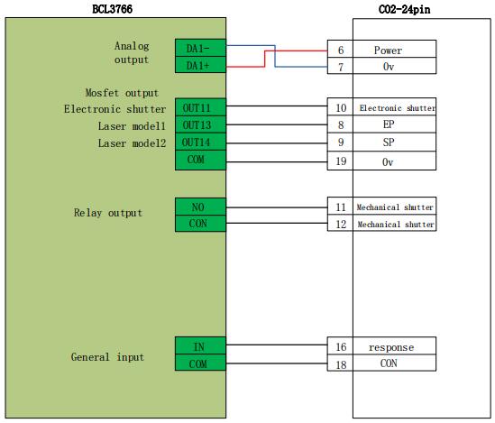
Note:
Part of the CO2 laser also supports PWM control mode, and specific wiring connection can refer to MAX laser wiring diagram.
When the laser you are using supports serial or Ethernet communications control, we strongly recommend that you connect communication ports (serial or network interface).
Using serial or Ethernet communication, CypCut software will monitor laser status in real-time, and can operate lasers by means of communication. Implementation including switch shutter (Emission), switch red (Guide beam), set the peak power (Current) and other actions, no longer need to connect the analog interface to control the laser peak power.
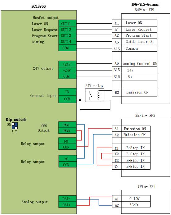
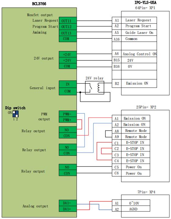
Recommended network interface of IPG-YLR series.
Notes
1. remote start button cannot be connected, especially when the laser is not in a good grounding , we do not recommend users to add remote start button, which is easy to cause the laser to produce failure.
2. PWM select 24V control (Dip switch: 1 pin is ON, 2 pin is OFF;Optionally select one among 3 pin and 4 pin is ON, then another one is OFF.
Note:
1. B2 pin of XP1 interface cannot connect Emission ON, then make sure that the Emission Status input port is set as 0 in "platform configuration tool", which means do not detect whether the shutter has been open or not.
2. PWM select 24V control (Dip switch: 1 pin is ON, 2 pin is OFF);
Note:
1. When the modulation signal select MODINPUTTTL interface, PWM select 5V control (Dip switch: 1 pin is OFF, 2 pin is ON;Optionally select one among 3 pin and 4 pin is ON, then another one is OFF.
2. When the modulation signal select 1 pin of I / O interface, PWM select 24V control (Dip switch: 1 pin is ON, 2 pin is OFF;Optionally select one among 3 pin and 4 pin is ON, then another one is OFF).
Note:
PWM of Bowflex laser select 24V control (Dip switch: 1 pin is ON, 2 pin is OFF);
2.5.8 JK/GSI-FL Series wiring diagram
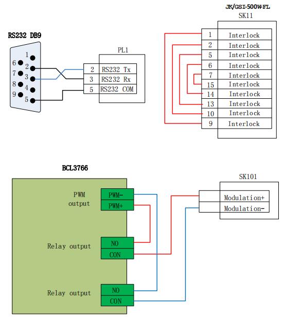
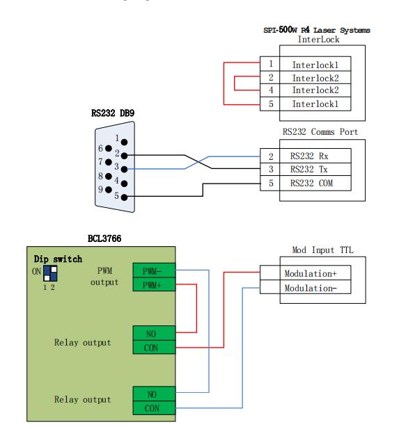
Note:
1. Several wires on SK11 which need to be interlocked, can connect the appropriate equipment to ensure safety interlock in accordance with the corresponding interpretation.
2. When the modulation signal select SK101 interface, PWM select 5V control (Dip switch: 1 pin is OFF, 2 pin is ON;Optionally select one among 3 pin and 4 pin is ON, then another one is OFF).
3. When the modulation signal select 16 pin of PL5 interface, PWM select 24V control (Dip switch: 1 pin is ON, 2 pin is OFF;Optionally select one among 3 pin and 4 pin is ON, then another one is OFF.)
2.5.9 Rofin fiber laser wiring diagram
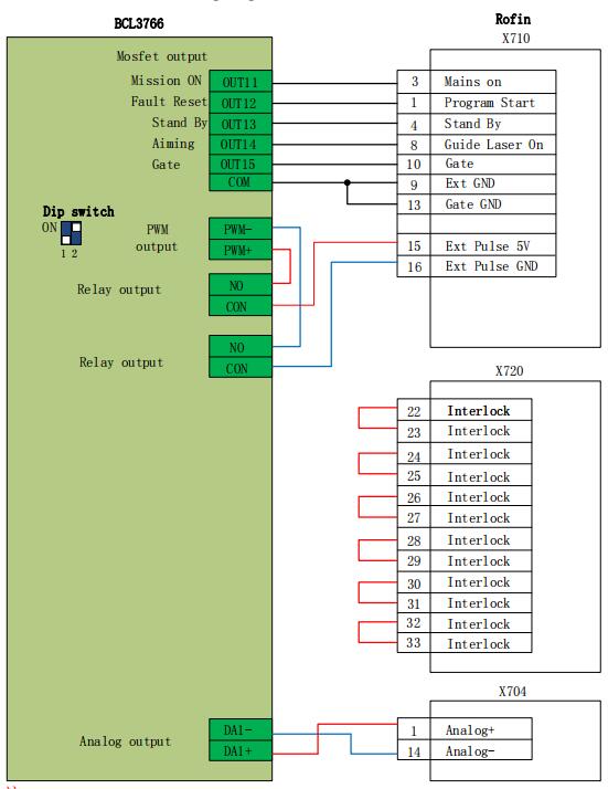
Note:
1.Several wires on X720 which need to be interlocked, can connect the appropriate equipment to ensure safety interlock in accordance with the corresponding interpretation.
2. PWM of Rofin laser select 5V control (Dip switch: 1 pin is OFF, 2 pin is ON;Optionally select one among 3 pin and 4 pin is ON, then another one is OFF.)
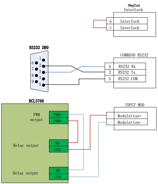
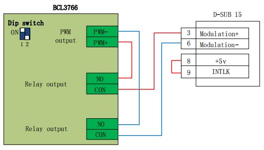
Note:
1. Raycus new lasers need to use 24VPWM signal control, while the old ones use 5V PWM signal. And new lasers can use the serial port control only before the key switch is in the REM state, while key switch of the old ones is in the ON state. It will indicate whether the laser is 24V PWM interface control or not; when it’s not indicated or marked with 5V, 5V control mode can be applied totally.
2. PWM select 5V control (Dip switch: 1 pin is OFF, 2 pin is ON;Optionally select one among 3 pin and 4 pin is ON, then another one is OFF.)
3. PWM of Max laser select 24V control (Dip switch: 1 pin is ON, 2 pin is OFF; Optionally select one among 3 pin and 4 pin is ON, then another one is OFF.)
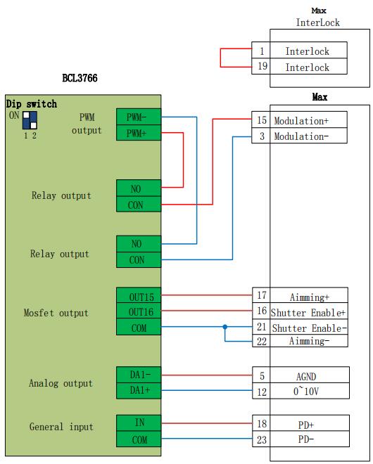
Note:
1. PD+PD- is a laser alarm output, connected to the input of BCL3766 External IO Board any interface, and with setting a custom laser warning (normally open) in "Platform Configuration - Alarm - Custom Alarm".
2. Red and Laser On enable GND can be incorporated together into any COM port of BCL3766.
3. PWM of Max laser select 24V control (Dip switch: 1 pin is ON, 2 pin is OFF;Optionally select one among 3 pin and 4 pin is ON, then another one is OFF.)
When you install CypCut software, your default selection is platform configuration tool.
Click “start”- “all programs”- “CypCut software for laser cutting”- “platform configuration tool” (the icon is ![]() ) to operate platform configuration tool software.
) to operate platform configuration tool software.
“CypCut software for laser cutting” in the path is the name of software. Different customers have different software names.
Before operate platform configuration tool, password box will appear as shown below:

Input password 61259023 and click “OK”, and you can start configuration of platform parameters.
Notes:
users should do parameter configuration based on actual configuration of cutting platform and wrong configuration may lead to unpredictable consequence!
In the platform configuration, the orange background color represents the input port configuration, the green background color represents the output port configuration.
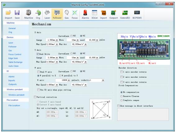
Main interface of platform configuration tool is information overview; The left and the upper convenient buttons are for entering various parameters setting page; green selected box as shown in the figure above is convenient button for controlling laser, height controller and adjusting auxiliary gas. Click left “config file” button to locate Data file.
Double click information overview to enter into parameters setting page for current information, such as: double click “mechanism” to enter machine setting page.
Click “Load” button to open existing configuration files; Click “Save” button to save information.
Notes:
1. Data files include various configuration information of CypCut software.
2. Data files backup function is in CypCut software ---- "File" ---- "parameter backup".
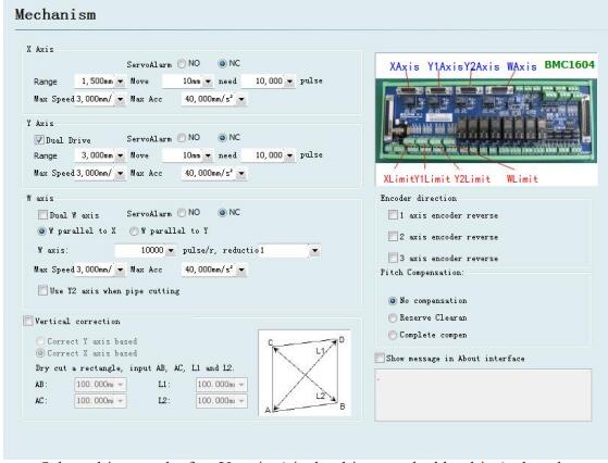
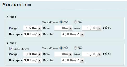
Select drive mode for Y axis (single drive or double drive), based on mechanical structure, and then configure information of rotation axis.
X axis range: Width of rectangle on CypCut painting interface. After start software limit protection, max motion range for X axis.
Y axis range: Height of rectangle on CypCut painting interface. After start software limit protection, max motion range for Y axis.
Pulse equivalent: Pulse count sent for 1 mm motion. Count automatically by actual motion distance and pulse count, and millimeter value can be set as four digits after the decimal point. Pulse equivalent= pulse count/ millimeter value.
Servo alarm: Select servo alarm signal logic, or close servo alarm feedback. Speed limit: limit max speed and acceleration for CypCut software.
Pitch Compensation: Error compensation for Interferometer data.
Verticality correction: When installation of X axis and Y axis is not 90o, the deviation can be eliminated through “Verticality correction”.
Forced open software limit: Enforce to open software limit function, and prevent users from manually switching the software limit in the master interface of CypCut.
Prompt user to return to origin after booting: Prompt the user to do the operation of returning to the origin each time you open the software.
Return to origin in the way of alarm: Prompt the user to do the operation of returning to the origin in the way of alarm each time you open the software.
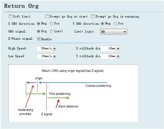
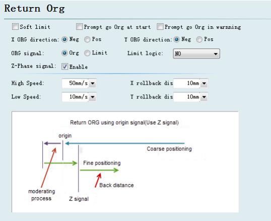
ORG direction: Different type can select different rollback to origin direction.
Back to origin direction determines which quadrant tool coordinate is in. For example, if X axis and Y axis select negative back to the origin, tool motion is in the first quadrant.
ORG signal: if users select limitation signal, origin switch can be replaced by limitation switch in the process of back to origin to realize coarse positioning.
Z direction signal: whether to use Z direction signal and sampled signal determines specific process of back to origin. The system will show a whole process on an image based on different back to origin way.
Fine speed: As shown in the green section of the figure, approach the origin slowly and 10mm/s is recommended.
Coarse speed: As shown in the blue section of the figure, approach the origin fast and 10mm/s is recommended.
Rollback distance: A distance for back in the motions of back to origin can ensure distance of mechanical origin leaving a distance from position limit switch.
Limit switch logic: Set logic of X, Y, Z axis limit, and origin signal.
CypCut provides different lasers configuration for YAG, CO2, IPG, Raycus, and SPI, other fibers, and different fiber types correspond to different parameters.
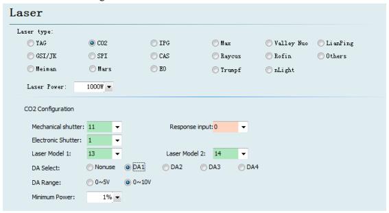
Mechanical shutter: Set output port for controlling mechanical shutter.
Electrical shutter: Set output port for controlling electrical shutter.
Response input: Set output port for response signal after opening mechanical shutter.
Laser Model: Set laser form as continuous wave, gate pulse and strong pulse through laser model 1 and laser model 2.
DA Select: 1604V2 card provides 2 interfaces of analog quantity and any interface o f output power controlling laser.
DA Range: Set analog quantity range of controlling laser power.
Minimum Power: Set minimum limit for pulse power.
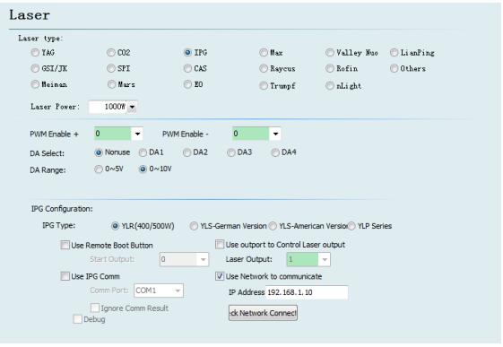 PWM enable signal: Select a relay output port as PWM enable switch, which can avoid laser leakage or wrong trigger under modulation mode.
DA Select: 1604V2 card provides 2 interfaces of analog quantity. Any interface can control laser peak power. Don’t use this port when using serial port or n e t w o r k remote control.
IPG fiber laser configuration: Remote start button:
After starting IPG remote control, CypCut software will monitor the state of lasers in real time and can operate lasers by means of communication. Motions, such as Emission, Guide beam, Current, etc, are realized. After selecting this option, DA port will be not available.
IPG remote control provides serial port and network, so users can set serial port or network IP address based on actual condition. If communication of PC, laser and BCS 100 applies network communication, please pay attention to don’t repeat segment. For example, if height controller segment is 10.1.1.x, and then laser can be set as 192.168.1.x. From the perspective of system stability, network is recommended.
If using serial port communication, please pay attention to shell and shielding layer of serial port connector must be ground connection.
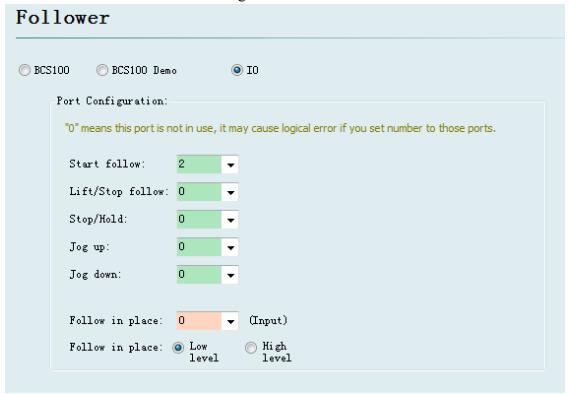
CypCut also supports input/output port to control height controller of other brands. Users can set the output port of following, rise (close following), stop (Hold), move up and down by clicking, and input port of following signal, by themselves.
Follow: open the input port for following.
Retract: set output port for raising (close following).
Stop/ Hold: Set output port for stopping Z axis motion.
Jog up: Set output port for manually controlling Z axis raising.
Jog down: Set output port for manually controlling Z axis declining.
Tracking in place signal: Set input port for collecting and following signal.
Tracking in place signal level: Set effective mode for controlling signal level.
Notes: If port is set as “0”, it means it is not available. If there is no this signal, please don’t set randomly, otherwise it may cause logical error!
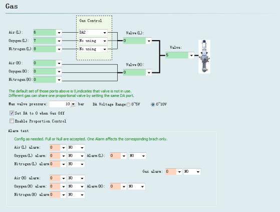
Valve:Set the total output port for auxiliary gas correspond to switch.
High pressure valve and low pressure valve: Set the output port for high pressure gas and low pressure gas.
Air Port: Set output port for air selection.
O2 Port: Set output port for oxygen selection.
N2 Port: Set output port for nitrogen selection.
DA Pressure:Users can select two interfaces of analog of 1604 card to regulate auxiliary gas pressure
Alarm detecting: Choose input port for gas alarm.
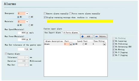
When the machine operates, the title bar will display a yellow warning message. You can customize the display
If X or Y axis of the platform structure apply a bilateral drive, you can set up a dual-drive shaft position excessive deviation alarm. If the dual-drive error reaches a certain value (allowable deviation) and continues for a certain period of time (duration time), the system will generate a "dual-drive shaft position excessive deviation alarm". If the deviation reached the maximum deviation value (maximum deviation) in a moment, the system will immediately generate an alarm.
Configure input port for emergent stop button, and here emergent stop is an input signal. If input port is active, emergent stop alarm will be generated.
After input port is active, the system will enter a mode of inspection, the maximum speed and maximum power will be restricted.
Users can add other types of alarm in “customized input alarm” and input alarm name in alarm description. Select port number and level detection type corresponding to alarm. General customized alarms include lack-voltage alarm, excessive temperature alarm, laser head collision alarm, etc.
The allowable maximum deviation, after enable the function of gantry synchronization.
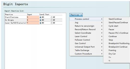
Click on the "Function Select" button, users can select the function name of the input port in the drop-down list, and then configure the corresponding input port and level detection.
Some functions of switching are divided into four sub-items, such as a laser switch, as shown below:
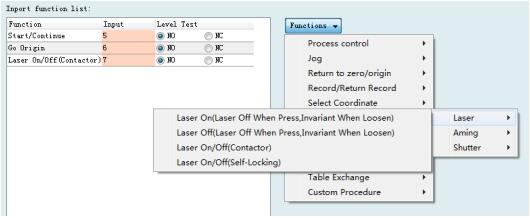
Each instruction is shown as below, please select according to your needs.
It’s in the following table
| Function Name | Instructions |
| Laser on (press on, loosen off) | Press the button: Open the corresponding function; Loosen the button: Not perform any action. |
| Laser off (press off, loosen invariant) | Press the button: Close the corresponding function; Loosen the button: Not perform any action |
| Laser on/off (switch) | Press the button: Open the corresponding function; Loosen the button: close the function. |
| Laser on/off (Lock) | Press the button: Open the corresponding function; press again: close the function. |
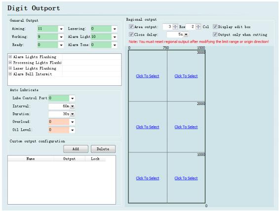
Aiming: Set output port for beam switch.
Laser instructions: After port configuration, corresponding indicator light will
blink during lightening.
Work instructions: After port configuration, corresponding indicator light will
blink when processing.
Alarm light: After port configuration, corresponding indicator light will blink
during alarming.
Alarm tone: After port configuration, corresponding bell will ring during
alarming.
After the port is configured, start time from opening the CypCut software. And then close, after opening the corresponding output port during each interval time and maintaining the setting output time.
Configure custom output port. The control buttons of custom port is displayed at the numerical control page of CypCut software. This custom port can choose the control mode of self-locking or contactor.
Regional output is mainly used for dust removal with machine. When laser starts, cutting head moves to area A (as shown in figure above), and corresponding “output port 12” of the area will be open; if trace moves from area A to area B, “output port 12” will be closed immediately, and “output port 15” will be open immediately. Output port closed belated: when area switch, the output port of last can not be closed immediately.
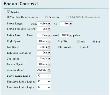
Focus adjustment range: Set software limit and stroke of the focusing motion.
Focus location after reset: define the origin corresponding to focus scale.
Pulse equivalent: Set the distance of movement focus corresponding to the number of pulses per revolution of the drive.
Return ORG direction: upward homing is negative direction, downward homing is positive direction.
Return ORG sampled signal: choose limit switch or origin switch as sampled signal.
Coarse positioning speed: quickly find the speed of origin switch when homing.
Precise positioning speed: Slowly precise positioning speed after find the origin switch.
Rollback distance: Reverse motion distance after completing precisely positioning.
Jog speed: Speed of clicking motion focus.
Positioning speed: Empty traverse speed when focus moves.
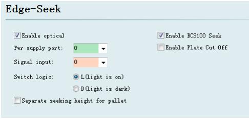
Optical edge seeking and capacitance edge seeking can be used after enter the set of edge seeking ,optical edge seeking must applies Omron E3Z-L61-type diffuse optical switch; capacitance edge seeking must applies BCS100 V3.0 height controller.
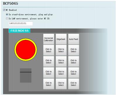
BCP5045 numerical control panel can be activated in numerical control panel interface. When used in a stand-alone environment, CypCut software will adaptively match the Mac address of BCP5045 numerical control panel, and automatically connect the control. When BCP5045 is used in LAN environment, please enter BCP5045 device ID number. BCP5045 is in total of 12 custom keys, which can be configured as a control button of double exchange workbench or other custom PLC.
Connect BCL3766 External IO Board and BMC1604V2 control card with
C62and C37 cables, and provide 24V power for BCL3766 External IO Board. Before turn on system power, please confirm whether power connection is correct or not and whether positive and negative polarity of power is short circuit or not.
Notes: Prohibit plugging BMC1604V2 card, C62 and C37 cable with electric heating!
Start computer and CypCut software. Click “file” in menu above→“Diagnosis”.
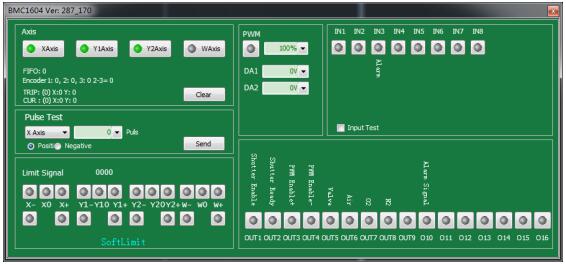
Please check in sequence positive/negative/origin switch of each axis, input signal, output signal, DA signal, PWM signal and servo-enabled signal.
For machines of double shaft drive, count value of encoders of two axes can be reset through 【reset】 button. Then send 1000 test campaign about the status of each axis, and ensure feedback pulse value and sent pulse value of encoder is in accord.
Setting method can refer to Appendix 7.1 "Scan cut" introduction file for more details.
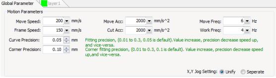
First, recommend setting servo driver parameters as conservative values. Also set the parameters of CypCut as conservative values. Click “Layer” → “Global parameter” on CypCut. Parameter setting is shown as below:
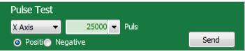
Use pulse test function, test whether pulse equivalent of the system is set correctly or not, click to test whether the direction and motion of each axis is normal or not.
Dual-drive machines do not install the electric motor at first, with no-load operation. Be sure to confirm the rotation direction and mechanical installation method of electric motor is well, and then install the motor.
When it have been confirmed the limit origin signal is normal, make each axes of the machine home origin and build machine coordinate system.
Use control panel on the right of CypCut software to click manually, rise and fall cutting head, switch gas, switch shutter, switch beam, laser on, and conduct each test by the operation of changing fixed fire power etc. Confirm the system can normally control laser, height controller, gas valve, etc.
Machine inertia ratio is a key indicator we measure the machine characteristics.
Using Servo Tools of Friendess, we can very easily calculate the inertia ratio of the machine for each axis. Servo Tools can be downloaded in http://downloads.fscut.com/.
As shown below:
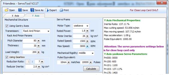
When inertia ratio is less than 200 percent, the device is light loaded, and enables high-speed cutting.
When inertia ratio is greater than 200% but less than 300 percent, the device is medium loaded, lose some precision during high-speed cutting, and need to appropriately reduce processing acceleration and FIR frequency.
When inertia ratio is greater than 300% but less than 500 percent, the device is overloaded, unable to achieve high-speed cutting.
When inertia ratio is greater than 500%, there are serious design flaws, servo is difficult to complete setting in a short time.
The maximum supported machine cutting speed, the maximum air shift speed, and the maximum acceleration can also be simply calculated by Servo Tools. These three parameters can be directly applied to control parameters in the software.
Experienced users can also accurately calculate the inertia ratio through testing software coming with servo.
Notes: the servo parameters calculated by Servo Tool is only used for the closed-loop card. Users of open-loop card, please set servo parameters based on position mode.
First, debuggers should be familiar with servo and can use professional servo
software to debug servo. For example, Panasonic servo comes with PANATERM testing software and Yaskawa servo comes with SigmaWin+ testing software. This
can simplify debugging.
STEP1: Open 【gain adjustment】 interface in PANATERM software. Open【real time automatic adjustment】 function of target axis, to automatically estimate inertia ratio.
STEP2: Rigidity is set as conservative value. For example, it can be set as level 13 first. Then click to move this high-speed axis with CypCut software. Observe whether axis is with abnormal sound and vibration, etc. Raise rigidity slowly. When the axis is with abnormal sound or vibration, level 1~2 should be declined to guarantee system stability. The final level should not be level 10 and more than level 20. If it’s dual-drive shaft, it starts moving only after modify two pairs of drive shaft parameters.
STEP3: After rigidity of X axis and Y axis is tested, set rigidity level as the same
level to guarantee response of two axes are the same. The smaller rigidity is standard.
For example, X axis is level 19 and Y axis is level 16. Finally, set X axis and Y axis as level 16.
STEP4: Close 【real time automatic adjustment】 and save parameters.
Yaskawa servo debugging is similar with the Panasonic. However, there is some difference. The difference is as below:
SigmaWin+ cannot be used to dual-drive axle ratio estimation, and advanced auto-tuning. Inertia ratio calculation tool, Servo Tool can be downloaded from the official website of Friendess to roughly calculate the inertia ratio for each axis. Advanced users may also accurately calculate the inertia ratio, based on a change of acceleration torque and acceleration time, by themselves.
We suggest closing Pn140 model tracking function.
We suggest closing Pn170 free adjustment function.
Yaskawa servo does not introduce rigidity and can set the following parameters based on Panasonic servo rigidity: Pn102 position loop gain: Correspond to pr100 of Panasonic.
Pn100 speed loop gain: Correspond to pr101 of Panasonic.
Pn101 speed loop integral time constant: Correspond to pr102 of Panasonic.
Pn401 Torque filter time constant: Correspond to pr104 of Panasonic.
The table is as below, and you should pay attention to unit and decimal point.
The unit of Yaskawa speed loop integral time constant, Pn101, is 0101 ms, while the one of Panasonic is 0.1 millisecond.
Delta servo debugging can also refer to the rigidity table of Panasonic. The reference method is shown as below:
The parameter P2-00 KPP is the equal of the position loop gain of Panasonic.
Though its unit is rad/s, actually, It's 1/s. For example, when the P2-00 KPP= 90, it’s the same as Pr100=900 of the position loop gain of Panasonic.
FSCUT2000C system mainly opens these four types of motion control parameters, such as speed, acceleration, FIR frequency, corner and circular accuracy, to users to adjust. Other sports-related parameters have been optimized internally without needing user settings. The meanings of these four parameters are shown as below:
| Name | Introduction |
| Move speed | Maximum speed of air moving, can be directly fill with the maximum move speed calculated by Servo Tools software. |
| Move acceleration | Maximum acceleration of air moving, can be directly fill with the maximum move acceleration calculated by Servo Tools software. |
| Max acceleration | Maximum acceleration during processing, directly determines the time of acceleration and deceleration of the turning movement during cutting. Adjust by observing the torque curve of servo. |
| FIR frequency | Suppress filter frequency of machine vibration. The smaller the value is, the more obvious the effect of suppressing the vibration is, but which will make the time of acceleration and deceleration longer |
| Circle precision | Arc accuracy limit. The lower the value of the arc precision, the more obvious the limit of arc speed is. |
| Corner precision | Fit with corner precision by NURBS curve. The lower the value is, the closer the corner is closed to sharp corner, but the deceleration will be more significant. |
The speed of high-clicking can be set as high as possible, such as 500mm / s.
When complete a click, moving distance is required to be long enough, in order to ensure that speed can be accelerated to the setting value.
Observe the torque curve of click movement by the servo debugging software.
For example, if the maximum torque is less than 80%, appropriately increase the processing acceleration; if the maximum torque is higher than 80%, appropriately reduce the processing acceleration.
Adjust the acceleration, until the maximum torque nearly is 80%. Generally, the processing acceleration withstood by lead screw is not more than 0.5G. Rack and pinion
generally is not more than 2G.
Directly fill the maximum acceleration calculated by ServoTool software, or appropriately increase the move acceleration on the basis of processing acceleration, for example, set as 1.5 to 2 times of the processing acceleration. It’s required that the maximum torque of the servo is not more than 150%, and the mechanical structure does not occure significant deformation and vibration under this acceleration. Screw affordable air movement acceleration generally is not more than 0.5G. Rack and pinion generally is not more than 2G.
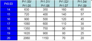
When you set up the FIR frequency parameter, you can cut a sample image. It’s proposed that, at the beginning, turn down the laser power, and mark the plate. Observe the accuracy of marking path. Cutting sample image includes various sized small round, regular 6-gon, regular 12-gon, star, rectangular, etc. As shown below:
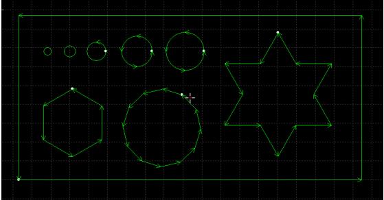
Adjust the FIR frequency as high as possible in the case of no affecting the accuracy. It is required the corner does not generate waves when cutting a rectangle, polygon and star. It can be set according to experienced value of the following table, Or debug the FIR frequency within the upper and lower two ranges after determining a processing acceleration. These two parameters, processing acceleration and FIR frequency, must be matched, with never transferring one value quite large and another value quit small among these two parameters.
| Level | 1 | 2 | 3 | 4 | 5 | 6 | 7 | 8 | 9 | 10 |
| Move acc(G) | 0.1 | 0.2 | 0.3 | 0.4 | 0.5 | 0.6 | 0.8 | 1 | 1.5 | 2 |
| Move Freq(HZ) | 2 | 3 | 4 | 5 | 5.5 | 6 | 6 | 6 | 7 | 8 |
Generally, it’s not recommended that users modify the precision of arc and corner. Under some special circumstances, you can fine tune these two parameters within the range of default parameters.
If you are not satisfied with the accuracy of the arc, you can turn down the arc precision parameters, at the same time the speed of process arc will be limited. The smaller the value is, the more obvious the speed limit is. If you are not satisfied with the accuracy of the corner, you can turn down the corner precision parameters, at the same time the speed of turning the corner will decline. The smaller the value is, the more obviously the speed declines. The higher the value is, the closer the corner will be to a fillet.
1.“desktop” of computer→ click right in “my computer” →“attributes” →“hardware” → “device manager”. Click “operation” → “Scan for hardware changes”.
See whether there is motion control card, as shown below: If BMC1604V2 motion control card can be found in device manager, please try reopening Cypcut software.
2.Observe the blinking state of 2 small lights (LED7,LED8)on top of BMC1604V2.
The position of lights is shown as below:
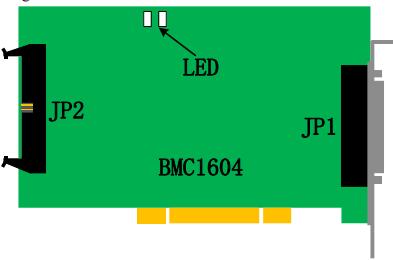
The representative state of LED blinking is shown as below:
| Blinking State | Meaning | Solution |
| 1 blink 1 blink | running normally | normal |
| 1 blink 2 blink | BMC1604 and BCL3766 work abnormal | rewiring |
| 1 blink 3 blink | unsupported USB | back to repair |
| 1 blink 4 blink | FPGA BOOT data transmission error | back to repair |
| 1 blink 5 blink | FPGA BOOT initialization error | back to repair |
| 1 blink 6 blink | FPGA BOOT unable to complete | back to repair |
| 1 blink 3 blink | ARM upgrade failed | back to repair |
| 1 blink 4 blink | file system formatting error | back to repair |
3.If LED is one flash and one flash (alternately flashes), which indicates BMC 1604V2 card is normal. Maybe PCI slot is bad contact. We suggest reinserting board card or replacing PCI slot after computer switches off.
The system defines that pulse equivalent is the command pulse count sent after 1mm movement.
The maximum pulse frequency of BMC1204 motion control card is 3Mpps.
Assume the maximum operating speed designed by the system is 1000mm / s. Then the pulse equivalent for each axis should not exceed 3Mpps / 1000 = 3000 Pulse / mm.
Under the permitted circumstances, we suggest set the pulse equivalent in 1000 ~ 2000 Pulse corresponding to per 1mm, and thus pulse sequence can be more continuous. Please try not to set the pulse equivalent as 200Pulse / mm or less.
Set pulse equivalent of X axis and Y axis as the same as possible, which is helpful to reduce truncation error calculated by the system.
In Cypcut, we use node mode to observe this graphic. If nodes are too many and graphics consist of many micro-segments, please perform curve smoothing on graphics and then process them.
Check whether the unreasonable delay is set or not, or the unit is misread, for example, set 200ms as 200s.
If the Z-axis has pause during the movement of lifting and descending, please check the program version of BCS100 height controller. If It’s BCS100 V2.0 height controller, please make sure the program was upgraded to the version of V802 or later.
Opening laser after blowing for a long time, please check the serial communication of laser is available.
If machine allows, improve FIR frequency and reduce time of acceleration and deceleration.
Properly increase turning precise parameters, and make high-speed smooth transition in sharp corner with Bezier curve.
Modify the mapping way, processing the circle overcut by the example as shown below.

Modify power curve, turn down laser power when speed declines.
Add cooling points on the corner, further processing after blow to cool for a period with light off.
Determine correct laser configuration in the platform configuration tool (YLS series of IPG has difference between German version and American version)
Determine whether serial port or Ethernet communications is applied and communications port is configured correctly.
Determine whether the DA signal control is applied to control the peak power, DA is selected correctly.
PWM-enabled and light-enabled is configured correctly.
Modify the output value of DA and PWM in the interrogation window of CypCut software (file—interrogation window). Use multi-meter to test whether DA of BCL3762 terminal block and voltage of PWM output port is normal or not.
If PWM output voltage is too low or the DA signal has no output, try to replace another interface of PWM or DA.
If it’s hardware failure, please contact our technical support or apply for repair.
Check the connection of PWM, serial cable and laser control signal lines.
Make sure serial cable use a shielded cable. 2 pin and 3 pin need to be cross.
Use the matching software coming with laser to do self-checking and to check light change, and to judge whether laser is working normally.
In the case of serial communication, not allow to open multiple software to communicate with lasers at one moment.
In the case of no serial port communication, you can click debug mode to view the sent instructions and the response of the laser.
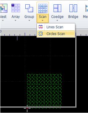
CypCut6.3.495 later version adds new functions: Scan cutting, also called fly cutting. Scan cutting of regular array pattern (suit for sheet metal) and naturally successive cutting of arc can be achieved by this function, thus greatly enhancing the processing efficiency. Function buttons are shown in the area of the following figure.
1. Linearly same-direction-grouping scanning: After the rectangular array is selected, set as linearly same-direction-grouping scanning. During the actual cutting process, rectangular will be divided into four direction scanning movement. Move of the middle section is not acceleration and deceleration shift, with just opening and closing the light.
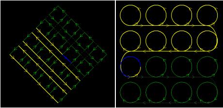
2. Naturally successive cutting of arc: After the circle array is selected, set as naturally successive cutting of arc. Actual cutting is the same as connecting all circle or arc with a straight line. There’s no acceleration and deceleration during processing, with just opening and closing the light.
You must set the number and direction of encoder feedback pulses correctly before using the scan cutting function! The setup method is shown as below:
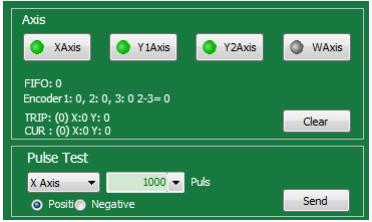
1. Open the diagnostic window CypCut of software, and send 1000 pulses to the X, Y-axis respectively in the "Pulse Test" module.
2. Judge whether it’s correct by encoder feedback value of "motion axis" and polarity. (Note: Sending positive feedback 1000 should be 1000 but -1000)
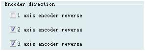
3. If the pulse feedback transmitted forward is negative, enter “the platform configuration tool - Machine page” to reverse the encoder corresponding to the number of axis. (Note: Have to set synchronously the encoder feedback of the second shaft and the third shaft in case of double-drive machine).
4. If the feedback is not 1000 after you send 1000 pulses, you need to adjust the servo parameter, while Panasonic is Pr011, Yaskawa is Pn212, Delta is Pn146. Set it as 1/4 of command pulses number per revolution. Panasonic A5, for example, it’s ok set Pr011 (encoder feedback) as 1/4 of Pr008 (pulse number per revolution). Yaskawa can be quickly set by installation wizard of
SigmaWin + software
Since the unevenness of screw, rack and other mechanical components exists, there is often a bias the actual characteristic and nominal features. When high precision is required, the actual deviations is required to be measured by a laser interferometer and other precision instruments, and then be compensated by the numerical control system, so as to achieve the purpose of reducing the deviation.
CypCut laser cutting system provides a complete and easy to use pitch compensation function, can easily control the machine to run in accordance with the requirements of the laser interferometer, and can directly read the data files outputted by laser interferometers, such as Renishaw, API, Agilent, OptoDyne. Even in the absence of laser interferometer supporting, reverse error compensation can also be set separately.
Before measurement error, we must first determine the machine origin. Screw pitch compensation is compensated by the machine origin as a reference. If the origin used by error measurement is different from the origin operating after machine compensation, then the pitch compensation will become meaningless. The machine homing origin can be set in the platform configuration tool of CypCut, as shown below:
As long as conditions allow, be sure to select "Use Z signal", which will greatly enhance the accuracy of homing origin. BMC1604V2 motion control card matched with CypCut provides encoder input to each axis, to extremely ensure accuracy.
Please select the direction X and Y axes home origin based on machine actual design. The direction of homing origin directly determines in which quadrant of the coordinate system the machine will run. If you select the "negative direction" to home origin, then the machine will run in the range of positive coordinates, otherwise the machine will run in the range of negative coordinates.
If possible, please repeatedly home origin by CypCut, then measure the accuracy of homing origin by laser interferometer. Usually, the position of every homing origin does not differ more than 5 microns.
Due to the processing precision and assembly errors, often, there’s difference between the pulse equivalent calculated by theory and the actual machine pulse equivalent. The pulse equivalent can be accurately measured by laser interferometer.
Make the machine runs at a distance by transmitting a specified number of pulses to the motor. For example, transmit the number of pulses which can make servo motor run a circle, and then measure the distance between the two points by the interferometer. It’s ok to fill the ted number of pulses and the distance in the platform configuration tool.
The method of sending a fixed number of pulses in CypCut is to open the "File" - "Diagnosis", select shaft as shown in the following figure window, input the pulse number, and click "Send."
The error is measured by the interferometer, commonly known as "Open interferometer." Generally, control the machine to stay for some time at an interval distance by the numerical control system, and then laser interferometer can measure the actual position of each point. The correspondence table of the theoretical position and the actual position can be obtained after all location measurement has been completed.
Most of the laser interferometers, such as Renishaw, must first set travel range, test interval and time spent at each point before starting the test, for example, stay one second every interval 30 mm. Laser interferometer decides whether to be measured by determining the separation distance and dwell time.
Firstly, determine several parameters:
Travel range. The total travel range of preliminary measurement, generally is set slightly smaller than the stroke of the machine design.
Measurement interval. Theoretically, the smaller the measurement interval is, the more accurate the results is after the compensation; but the smaller the measurement interval is, the more the point required to be measured is, and also the longer time it takes. Recommended interval value is between 10 mm to 100 mm.
Dwell time. The minimum dwell time of Renishaw default is two seconds.
Opens CypCut- "Numerical Control" - "light path adjustment" screen, and find the following window:
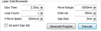
Herein, the travel range is automatically read, please set as same as the setting value of the interferometer, but pay attention to symbols. Input a negative value when forward home origin, whereas input a positive value. If input an error value, the system will prompt when you save.
Set the interval value as same as the value in interferometer. Otherwise, data may be undetectable.
Please set dwell time slightly larger than the "minimal stop cycle" of the interferometer, to ensure the interferometer can correctly identify each point required to be measured.
Please ensure cycle number the same as "Measurement times" set in the interferometer. Since CypCut only read once back and forth measurements, so the
first time data of the measured data of many times will be only read, when you import the measured data of many times into CypCut.
Gap adjustment means during reverse movement, movement will be continued along the original direction for 5mm, and then return 5mm, thereby eliminating the mechanical interval. This value should not be greater than the value of the interval value minus the tolerance window, otherwise the interferometer will mistakenly think that this is a point required to be measured.
Click the "Generate interferometer positioning program", and then the positioning program will be generated in the right window. Check the following conditions are true and correct and click "Run" to start the measurement.
1. The measurement axis has return to the origin. Be sure to measure from the origin
2. The interferometer is ready, and the parameters is matched with the parameters set in CypCut.
After the test is complete, save the measurement results from the interferometer software. The result is RTL format for Renishaw. Copy the files to a PC which CypCut is running.
The pitch compensation data files after obtained can be imported into CypCut.
CypCut can directly read files saved laser interferometer Renishaw, such as API, Agilent, OptoDyne. If you are using the interferometer file which cannot be read by CypCut, please contact us, we will try our best to solve it. The method of importing error data is as below:
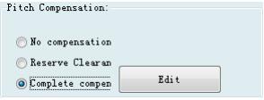
Open platform configuration tool, select the "complete pitch compensation" in the "pitch compensation" of "Mechanism " Interface, as shown below:
And then click on "View compensation data", and pop up the following window.
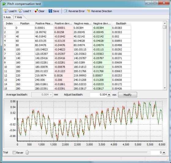
Click "Import X", which can import X-axis error data, and click "Import Y" which can import Y axis error data. The imported results will be displayed in lists and graphics after data completion.
If the position coordinates shown in the table is different with the direction of homing origin, the compensation results will be invalid. Generally, when importing data, CypCut will automatically determine the symbol of the position. If inconsistent, please contact us to solve it, or adjust the measuring range as same as the stroke range of the machine by modifying the measurement parameters of interferometer software, and then import the data.
1. Create an Excel spreadsheet, and save as xxx.xls or xxx.xlsx format. Data input format is shown as below:
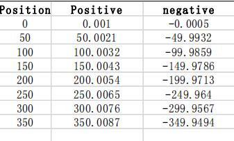
2. Open platform configuration of software – pitch compensation - Import above documents
1. Mechanism return to origin;
2. Set interferometer to get parameter;
3. Set parameter on optical adjustment interface of cypcut, generate interferometer locating procedure.
4. Use interferometer to measure error, get mechanism date;
5. Import interferometer data in the tool of platform configuration and save it;
6. Mechanism return to origin;
7. Use interferometer to measure error again, verify the result of pitch compensation;
1.The compensation without changing before and after Return to origin after compensation, than compensation data will be valid.
If set the pulse equivalent as 200Pulse / mm or less, compensation data will not be valid.
2. Error doubled after compensation
If it is found that the shape of the forward and reverse error curve is almost no change after compensation, but the value almost doubled and the distance between the two curves is also doubled (That is, reverse interval), it is likely that the sign of error value is reversed. In this case, click the "error value inversion", which can make compensation accuracy is greatly improved.
The reason for the problem is that the error data file provided to CypCut does not contain the measured value, while only contain the error between the measured value and the theoretical value. And the error may be found by the measured value subtracting the theoretical value, or the theoretical value subtracting the measured value, leading to import data which has two possibilities.
The pos file formats generated by API XD Laser Interferometer, as well as the lin file format generated by light moving OptoDyne, contains both the theoretical value and the measured value. So the question of error sign when reading would not arise.
3. Reverse interval doubled after compensation
If it’s found that the pros and cons have been improved after compensation, but the effect of improvement is not obvious, and the reverse interval has increased even with doubling trend, it is likely that the forward data has been compensated to the reverse, and the reverse data has been compensated to the forward. At this moment, please click the "exchange of pros and cons" to make
the positive and negative data (that is, red and green curves) reversed.
When the data sign tested by interferometer is inconsistent with the actual stroke range sign of machine tool, this situation most likely happens. The positive direction determined by interferometer is the direction of coordinate increasing, opposite to the direction of the machine coordinate increasing. CypCut has automatically handled this situation as much as possible, but it still cannot guarantee that all cases can be handled automatically.
4. The positive and negative curve is symmetrical after compensating.
If it’s found that positive and negative curves symmetrically change after compensation, the most likely reason is that the sign of forward error and reverse error is opposite, one of which is correct, and the other is wrong. This condition is considered to be very rare. In order to reduce the difficulty of customers understanding, CypCut has blocked the button which deals with this situation. If
this happens to you, please manually make the error of forward or reverse reversed before importing, and then import. Or contact us to help solve.
![]()
Masters in industrial manufacturing with 25 years of experience and 10+ awards!